
PoE Design in 2026: From a 13W Camera Board to the 90W Smart Building — What Hardware Startups Need to Know
For hardware startups building powered devices (PDs), the good news is that a compliant, EMI-passing PoE front end can now fit in roughly 1.6 cm × 3.2 cm of board space. The catch is that getting isolation, detection, and thermal design right the first time still separates products that pass certification from products that burn a respin.
PRODUCT DEVELOPMENT
Peakingtech Engineering Team
7/9/20267 min read
Quick answer: Power over Ethernet (PoE) lets one Cat5e/Cat6 cable carry both data and power, eliminating the separate AC/DC adapter for network-connected devices. In 2026, PoE design is being reshaped by three forces: the mainstreaming of 90W 802.3bt (PoE++), AI-driven power management at the switch level, and 10G PoE for Wi-Fi 7 and 8K surveillance. For hardware startups building powered devices (PDs), the good news is that a compliant, EMI-passing PoE front end can now fit in roughly 1.6 cm × 3.2 cm of board space. The catch is that getting isolation, detection, and thermal design right the first time still separates products that pass certification from products that burn a respin.
This article walks through both sides: the practical, board-level reality of designing a PoE powered device today, and the industry trends that should shape your product roadmap.
What Is PoE, and Why Does It Matter for Product Design?
Before PoE, any network-connected device — an IP camera, a wireless access point, a VoIP phone — needed two cables: one for Ethernet data, one for power. That doubled installation labor, constrained mounting locations to wherever an outlet existed, and added cost for the end customer.
PoE (Power over Ethernet) solves this by transmitting DC power over the same twisted pairs that carry data. A PoE system has two roles:
PSE (Power Sourcing Equipment): the PoE-capable switch or injector that supplies power.
PD (Powered Device): the endpoint — camera, AP, sensor, kiosk — that receives power and does the work.
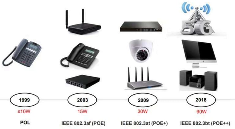
If you're a hardware startup, you're almost certainly designing on the PD side. And the standards ladder determines your power budget:
Standard Common Name Max Power to PD Typical Era
IEEE 802.3af PoE 15.4 W 2003
IEEE 802.3at PoE+ 25.5 W 2009
IEEE 802.3bt PoE++ (Type 3/4) up to 71.3 W delivered2018, mainstream now
In 2026, Type 4 802.3bt has crossed from "premium option" to enterprise baseline, with adoption reported above 60% in enterprise deployments and 48-port 90W switches becoming the new campus standard. That shift changes what customers expect your device to do — and how much power it's allowed to draw doing it.
Anatomy of a Modern PoE PD Design: A 13W Reference Case
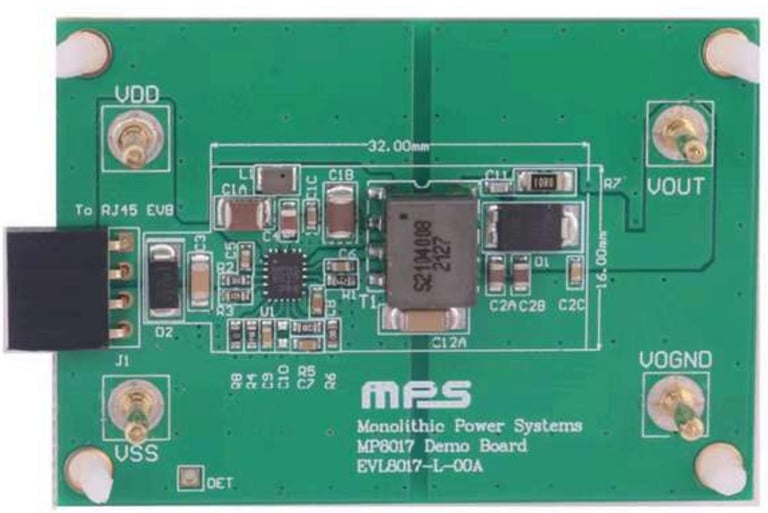
Theory is easy; shipping a board that passes conducted-emissions (CE) and radiated-emissions (RE) testing on the first spin is not. Let's look at what a compact, production-realistic PD power stage actually looks like, using a 13W-class flyback design built around MPS's MP8017 as a working example — a solution whose core power stage occupies just 1.6 cm × 3.2 cm.
The signal chain: from RJ45 to regulated rail
Power arrives on the Ethernet pairs and is tapped through the center taps of the magnetics inside (or beside) the RJ45 jack. Because 802.3af/at allows power on either the data pairs or the spare pairs — and with either polarity — the design runs each source through a diode bridge rectifier before feeding the PoE controller. Two bridges (one per pair group) OR-ed together guarantee the PD works no matter how the installer wired the far end.
From there, the PoE PD controller handles three jobs in sequence:
Detection. The PSE probes the line with a low voltage and looks for the 25 kΩ signature resistance. No valid signature, no power — this is what prevents PoE switches from frying legacy non-PoE devices.
Classification. A class resistor tells the PSE how much power the PD intends to draw, so the switch can budget its ports.
DC-DC conversion. Once the full 37–57 V line voltage is applied, an integrated flyback converter steps it down to the working rail — 12 V at 1 A in this reference design, at 86.5% full-load efficiency with a 500 kHz switching frequency.
The clever part: primary-side regulation
The reference design regulates output voltage using primary-side feedback from the main winding itself — no auxiliary winding, no optocoupler. The primary winding does double duty: power transfer and voltage sensing.
The trade-off is honest and worth understanding:
What you give up: feedback accuracy on the secondary voltage is somewhat reduced, and load regulation is slightly looser than an optocoupler-based loop.
What you gain: fewer components, a smaller and cheaper transformer (an EP7 core in this case, using an off-the-shelf common-mode transformer with a 24:12, 2:1 turns ratio and paralleled secondaries), and meaningfully less board area.
For cost-sensitive, volume products — cameras, sensors, controllers — that trade is usually correct. And when it isn't, the same controller supports optocoupler feedback for applications that demand tighter voltage accuracy and load regulation. Choosing between the two configurations early, based on your downstream circuitry's tolerance, is exactly the kind of decision that should happen in NPI review, not after EVT.
EMI without the usual crutches
The notable claim from this design — backed by official CE and RE test plots with comfortable margin under Class B limits — is that it passes emissions without a common-mode choke or ferrite beads, and with no RCD snubber on the switch node. Two features make that possible: active clamping and frequency jitter (spread-spectrum switching), which smears switching energy across the spectrum instead of concentrating it into failing peaks. A Y-capacitor across the isolation barrier provides the return path for secondary-side common-mode currents.
For startups, the lesson isn't "you'll never need a CM choke." It's that modern integrated PoE converters have moved much of the EMI battle into silicon — but only if the layout respects the reference design. This is where a one-sided component placement on a small two-layer board (the reference EVB is 60 mm × 42 mm with essentially all components on top) pays off in assembly cost too.
Scaling up: one family, four power classes
The same design philosophy scales across the 802.3bt range. In the MPS portfolio the progression looks like this: 13 W flyback (MP8017, EP7 core, ~86% efficient), 25 W flyback (MP8009, ~91%), and 51–71 W active-clamp forward designs (MP8030, up to 93.2% efficient on an EFD25 core). Notice the topology change: past roughly 30 W, flyback gives way to forward converters because efficiency and thermal density demand it. If your product roadmap includes a higher-power variant, choose your controller family with that migration path in mind — and note that if your device must accept either a PoE line or a local adapter, you need a controller with dual-input arbitration (MP8009/MP8030 class), because the basic 13W part can't distinguish the two.
A field warning worth its weight in gold
One veteran engineer's hard-won advice from deployment: use fully isolated PoE architectures, or non-isolated designs that buck from V+ with a shared ground plane — but avoid schemes that shift the low-side ground reference upward to reduce output voltage. Mixed-vendor installations with that architecture have destroyed equipment in the field. Isolation isn't just a compliance checkbox; it's interoperability insurance in a world where your customer plugs your device into a switch you've never tested against.
The 2026 PoE Landscape: What's Changing Above the Board Level
A great PD power stage is table stakes. What's changing in 2025–2026 is what the system expects from your device.
1. 90W is the new normal — and thermal design is the new bottleneck
With Type 4 PoE++ mainstream, product categories that were impossible on PoE — pan-tilt-zoom multi-sensor cameras, PoE-driven displays, edge compute nodes, even drone charging pads — are now routine. But 90 W over twisted pair means real current and real heat. Expect Cat6A-or-better cabling requirements, and budget serious attention to thermal paths in sealed outdoor enclosures. Single-pair Ethernet PoE (802.3bu-lineage) is simultaneously opening the low end for lightweight industrial sensors.
2. Switches are getting smart — your PD should be a good citizen
Modern PSEs perform real-time device fingerprinting from power signatures, predictive load balancing from historical draw patterns, and time-based or event-driven power scheduling (shutting down APs and displays after hours, power-cycling a hung camera remotely). Design implications for PDs:
Implement clean, spec-compliant classification so smart switches budget you correctly.
Tolerate scheduled power cycling gracefully — fast, corruption-free cold boots are now a feature, not a nicety.
Consider LLDP-based power negotiation for anything above Class 4; static class resistors leave power (and switch ports) on the table.
3. 10G PoE is arriving with Wi-Fi 7 and 8K video
Wi-Fi 7 access points needing 6 Gbps+ backhaul and 8K/H.266 surveillance cameras are pulling 10GBASE-T PoE into deployment. Higher data rates plus higher power over the same copper compounds the thermal and signal-integrity challenge — magnetics selection, return-loss budgets, and cable-side common-mode behavior all get harder together.
4. PoE as smart-city and industrial backbone
PoE is increasingly treated as a unified data-plus-power control plane: traffic sensors with 5G small-cell integration, digital-twin nodes, building automation actuators. For industrial products, that means designing for wider temperature ranges, surge immunity, and the isolation discipline discussed above.
5. Security is now a PoE design requirement
The zero-trust wave has reached the power layer. Deployments are adopting anomalous power-draw detection (an IP camera hit by ransomware often changes its consumption profile), stronger device authentication, and FIPS 140-3 encryption requirements in government projects. If your PD's power behavior is predictable and well-characterized, it's easier for security tooling to certify — one more reason to instrument and document your power profile during NPI.
What This Means If You're Building a PoE Product
Pulling it together, here's the checklist we run with clients at the NPI stage:
Pick your power class deliberately. Design to the class you certify, and use LLDP negotiation above 25 W.
Decide feedback architecture early. Primary-side regulation for cost and size; optocoupler for precision rails.
Respect isolation. Fully isolated or properly referenced non-isolated — never ground-lifting schemes.
Follow the reference layout, then verify. Integrated EMI features only deliver if placement and return paths match the datasheet's intent. Pre-scan before formal CE/RE testing.
Design for smart switches. Graceful power-cycle recovery, accurate classification, characterized power signature.
Plan the thermal path at 90 W. Especially for sealed and outdoor enclosures.
Prototype with production magnetics. Off-the-shelf transformers like the EP7 part above are great for speed, but lock the exact part number before DVT — turns ratio and leakage inductance are not interchangeable.
PoE in 2026 rewards teams that treat power as a first-class design domain rather than an afterthought bolted next to the RJ45 jack. The silicon has never made it easier to build a small, efficient, EMI-clean PD — and the market has never expected more from it.
SERVICES
Peakingtech © 2025. · Shenzhen, China · Privacy Policy · Terms of Service
Contact Form
Metal Parts


Peakingtech® is a registered trademark of Peakingtech Co in the United States.
COMPANY
CONTACT