Custom Plastic Enclosure Design and Injection Molding
From enclosure concept through mold design, tooling, and production — designed to fit your electronics and built to your finish specification.
Services › Plastic Enclosures
CONTRACT MANUFACTURING · SHENZHEN
Enclosure Design
Mold Design
Injection Molding
Rapid Tooling
Finishing & Assembly
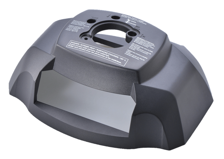
Plastic Enclosure
Tooling from $3,000 | Lead time from 4 weeks | Shenzhen-based
CAPABILITIES
From concept sketch to production-ready enclosure
Four integrated capabilities covering the complete enclosure development and production cycle — handled in-house, coordinated with your electronics build.
Enclosure Design
Full mechanical design of injection-molded plastic enclosures — from concept sketch or requirements document through production-ready 3D CAD.
All four capabilities available independently or as a complete package — from design through production.
3D CAD in SolidWorks and Fusion 360
Draft angle analysis and optimization
Wall thickness and rib design for structural integrity
Snap fits, bosses, and mechanical interfaces
Parting line and gating strategy defined at design stage
IP rating design — IP54, IP65, IP67 where specified
Tolerance stackup analysis for multi-part assemblies
Enclosure design files (STEP, IGES, DXF, engineering drawings) delivered to you upon completion — you own all design outputs.


Enclosure design files (STEP, IGES, DXF, engineering drawings) delivered to you upon completion — you own all design outputs.
Aluminum rapid tooling: from $1,500 · 2–3 week lead time
P20 steel production tooling: from $3,000, 4–5 week lead time
H13 / S136 hardened steel: from $8,000, 5–8 week lead time
Single and multi-cavity mold configurations
Side actions, lifters, and collapsible cores where required
Mold flow analysis before tooling commitment
First shots included in tooling cost
Complete mold design package from parting line definition through first shots — aluminum rapid tooling and production steel tooling both available.


Mold Design & Tooling
Per-part pricing quoted separately from tooling — depends on material, shot weight, and quantity. Typical range: $0.50 to $8.00 per part.
Pilot runs from 50 units — no high-volume minimum
Production runs: 500 to 100,000+ units
Machine tonnage: 50 to 850 tonnes — covers small to large enclosures
Materials: ABS, PC, ABS+PC, PP, Nylon, TPU and more
Color matching: RAL or Pantone reference
Surface finish: gloss, semi-gloss, matte, textured
In-mold labeling and insert molding available
Production runs from pilot quantities through volume — in your specified material, color, and finish.
Injection Molding Production


Finishing operations are coordinated with PCBA box-build assembly — finished enclosure and populated PCB assembled in the same facility.
Spray painting: solid colors, two-tone, soft-touch coating
Silk screen printing: logos, text, regulatory marks
Pad printing: curved surfaces and recessed areas
UV coating: scratch resistance and gloss enhancement
Ultrasonic welding: permanent assembly of plastic parts
Heat staking and press-fit hardware insertion
Laser engraving: permanent marking without inks
Post-molding processes that turn a raw molded part into a retail-ready product surface — painting, printing, assembly, and decoration.


Finishing & Secondary Operations
MATERIALS
Choose the right material for your enclosure
Six materials covering the full range of electronics enclosure applications — from standard consumer products to IP-rated industrial housings. Key properties and typical applications for each.
Acrylonitrile Butadiene Styrene
The default choice for consumer electronics enclosures — excellent processability, good surface finish, and wide color availability.
IMPACT RESISTANCE: Good — medium grade
TEMPERATURE RATING: Up to 80°C continuous
UV STABILITY: Poor — needs coating for outdoor
COST: Low — most economical option
TYPICAL FINISHES: Gloss, Semi-gloss, Matte, Painted
Accent colors are for visual differentiation only - all materials available in custom per RAL or Pantone specification.
ABS
BEST FOR: Consumer electronics, indoor smart home devices, desktop equipment enclosures, and products where cosmetic quality and painting adhesion are priorities. ABS paints and post-processes better than almost any other thermoplastic.
BEST FOR: Products requiring optical clarity (lens windows, indicator covers, display panels), high-impact resistance (portable or handheld devices), or elevated temperature environments (near heat-generating electronics, automotive interior). Also the preferred base material for PC+ABS blends.
IMPACT RESISTANCE: Excellent — 20× stronger than glass
TEMPERATURE RATING: Up to 120°C continuous
UV STABILITY: Moderate — UV-stabilized grades available
COST: Medium — 30–50% above ABS
TYPICAL FINISHES: Clear, Gloss, Matte, Coated
High-impact, optically clear engineering plastic — the choice when strength, transparency, or elevated temperature performance is required.
Polycarbonate
PC
BEST FOR: The most common choice for mid-range and premium consumer electronics enclosures where neither pure ABS nor pure PC is ideal. Smartphone cases, power tools, medical handheld devices, and IoT product housings all commonly use ABS+PC blends. Better dimensional stability than ABS with better moldability than PC.
IMPACT RESISTANCE: Very good — better than ABS alone
TEMPERATURE RATING: Up to 100–110°C continuous
PROCESSABILITY: Very good — lower warp than pure PC
COST: Low-medium — between ABS and PC
TYPICAL FINISHES: Gloss, Matte, Textured, Painted
The best-of-both material — combines ABS processability and surface quality with PC's impact strength and temperature resistance.
ABS + Polycarbonate Blend
ABS+PC
BEST FOR: Enclosures with integrated living hinges (PP is the preferred material for living hinge features), battery compartment doors, products with repeated snap-fit cycles, outdoor or industrial products with chemical exposure, and lightweight enclosures where density is a concern. PP is naturally waxy and difficult to paint — specify color in the material where possible.
IMPACT RESISTANCE: Good — excellent fatigue resistance
TEMPERATURE RATING: Up to 100°C continuous
CHEMICAL RESISTANCE: Excellent — resists most acids and solvents
COST: Low — comparable to ABS
TYPICAL FINISHES: Natural, Colored resin, Textured
Lightweight, chemically resistant, and fatigue-tolerant — the choice for enclosures with living hinges, snap-fit lids, or chemical exposure requirements.
Polypropylene
PP
BEST FOR: Structural components within an enclosure (mounting brackets, PCB standoffs, internal frames), enclosures with high operating temperatures, products requiring dimensional stability under mechanical load. Glass-filled PA66 (PA66-GF30) is commonly used for industrial and automotive electronics where both strength and heat resistance are required. Note: PA66's moisture absorption means dimensions should be allowed for in tight tolerance assemblies.
IMPACT RESISTANCE: Good — excellent with glass fill
TEMPERATURE RATING: Up to 130°C continuous
TENSILE STRENGTH: High — especially glass-filled grades
MOISTURE ABSORPTION: High — dimensions can change with humidity
COST: Medium-high
GLASS-FILLED GRADES: PA66-GF30 common for structural parts
TYPICAL FINISHES: Natural, Colored resin, Matte
High-strength engineering plastic with excellent mechanical properties — used where structural performance, heat resistance, or glass-filled reinforcement is required.
Nylon (Polyamide 66)
PA66
BEST FOR: Soft-touch grip surfaces on handheld devices, rubberized bumper zones on portable products, integral gasket features for IP-rated enclosures, cable strain relief boots, and any surface where tactile quality or impact protection matters. TPE/TPU is typically overmolded onto an ABS or PC substrate in a two-shot or insert molding process.
HARDNESS: 20–90 Shore A — specified by application
TEMPERATURE RATING: Varies — typically –40°C to 80°C
BOND TO RIGID PLASTIC: Excellent onto ABS, PC, ABS+PC
COST: Medium — two-shot or insert mold required
TYPICAL FINISHES: Soft-touch matte, Textured grip, Colored
Flexible, rubber-like materials used for overmolding onto rigid enclosures — creating soft-touch grips, waterproof seals, and impact-absorbing bumpers.
PE / TPU — Soft Overmold
TPE / TPU
For Maximum Impact Resistance
Material Decision Guide

Choose PC or ABS+PC alloy for high-impact and drop protection applications.

For Chemical Resistance
PP and PC offer excellent resistance to most chemicals and cleaning agents.
PP, Nylon (PA66) and ABS+PC perform well in elevated temperature environments.
For High Temperature Applications


For Lightweight Enclosures
PP is the lightest option, ideal for portable and battery-powered devices.


For Flexibility & Sealing
TPE/TPU is perfect for overmolding, seals, gaskets and vibration damping.
For Cost Efficiency
ABS offers the best balance of performance and cost for most applications.
OUR PROCESS
How we take your enclosure from design to first shots
Five defined steps — from your initial brief through mold design, tooling fabrication, and first shot approval. Your sign-off required before each stage proceeds.
Design Review & DFM
Timeline confirmed at DFM review stage — before any design or tooling cost is committed.
Timeline: 2–3 days
We review your brief, sketch, or existing CAD files for moldability. Draft angles, wall thickness, parting lines, and gating strategy confirmed before detailed design begins.


Your sign-off: Confirm design approach and DFM findings before Step 2 begins.
Timeline: 5–7 days
Full mold design package — cavity, core, runner system, cooling layout, and ejection system. Mold flow analysis run before any steel is cut.
Mold design


Timeline: 2–4 weeks
Mold tool machined from specified steel — aluminum for rapid tooling, P20 or H13 for production tooling. Precision EDM and CNC machining to tolerance.
Tooling fabrication

Timeline: 3–5 days
First plastic parts shot from the new tool. Dimensional inspection against design drawings, surface finish review, and fit check with your PCB or assembly. Your approval required before production begins.
First shots & approval
Timeline: 1–3 weeks
Approved tool runs production quantity. 100% dimensional sampling, cosmetic inspection per agreed standard, and coordination with PCBA box-build if applicable.
Production
RAPID TOOLING (ALUMINUM): 3–4 weeks
concept to first shots
PRODUCTION TOOLING (P20 STEEL): 6–8 weeks
concept to first shots
FIRST SHOTS TO PRODUCTION: 1–2 weeks
after your first shot approval
Timelines start from receipt of complete design files or approved 3D CAD. Long-lead components or design changes between steps extend timelines.
Your approval before every commitment
Nothing proceeds from design to mold design, or mold design to tooling fabrication, without your explicit sign-off. Every transition is a decision point — not an automatic next step.
All tooling produced for your project belongs to you. We store it at our facility between production runs, but you retain full ownership. Take it elsewhere if you choose — no restrictions.
The tool is yours — not ours
We run mold flow simulation on every new tool design before fabrication begins. Sink marks, weld lines, and fill issues are identified and resolved in simulation — not discovered on the first shot.
Mold flow analysis before any steel is cut
TOOLING & PRICING
What injection mold tooling actually costs
Three tooling tiers based on steel type, expected shot life, and production volume. All tooling belongs to you — we store it at our facility between runs.
Rapid Tooling
Aluminum — prototype and low-volume production
TOOLING COST: From $1,500
Expected shot life: 5,000 – 10,000 shots
Typical lead time: 2-3 weeks
Upgradeable: Yes — to P20 production tool
BEST FOR: Design validation · Pre-production.
P20 pre-hardened steel — standard production
Production Tooling
BEST FOR: High-volume · Glass-filled materials
H13 or S136 hardened steel — high-volume and abrasive materials
High-Volume Tooling


TOOLING COST: From $3,000
Expected shot life: 500k shots
Typical lead time: 4-6 weeks
Polishable: Yes — gloss and textured finishes
BEST FOR: Standard production runs
TOOLING COST: From $5,000
Expected shot life: 1kk shots
Typical lead time: 4-8 weeks
Steel hardness: H13: 48–52 HRC · S136: 50–54 HRC
All tooling belongs to you — regardless of which tier
Every mold produced for your project is your property. We store it at our Shenzhen facility between production runs at no charge. You can remove the tool at any time — no restrictions, no transfer fees.
Full legal ownership from completion of first shots
Stored at our facility at no charge
Removable at any time — no conditions
Per-part pricing — what it depends on
Per-part cost is quoted separately from tooling — the two costs are independent. A higher tooling investment in P20 steel does not mean higher per-part cost. Per-part cost is driven by four factors: material cost, shot weight (how much material is used per cycle), cycle time (how fast the machine can run), and production volume.
Material cost is the most significant variable. ABS is the least expensive common enclosure material. PC costs more per kilogram. Glass-filled nylon (PA66-GF30) costs more again. The difference between ABS and glass-filled nylon per-part can be 40–60% for the same shot weight.
Volume is the second most significant variable. Per-part cost at 500 units and per-part cost at 50,000 units can differ by a factor of three or more — the same machine setup cost spreads across more parts at higher volume.
We provide per-part pricing as a separate line item from tooling in every quote. You receive: tooling cost (one-time), per-part cost at your specified volume, and total cost for the order including any finishing operations.
About the prices shown
The tooling costs and per-part ranges shown are based on standard electronics enclosure complexity — two-part enclosures with no side actions, in common engineering plastics, at typical production volumes. Complex parts with multiple side actions, deep draws, tight cosmetic requirements, or engineering plastics with challenging process parameters will cost more. Simple parts will cost less.
Every project receives a specific written quote before any design or tooling cost is committed. The quote includes tooling cost, per-part cost at your volume, NRE for any secondary operations, and lead time. There are no costs that appear after the quote is agreed. If our initial estimate is wrong at quoting stage, we absorb the difference — not you.


Tooling cost confirmed at mold design approval — after DFM review and before any steel is cut.
INTEGRATED MANUFACTURING
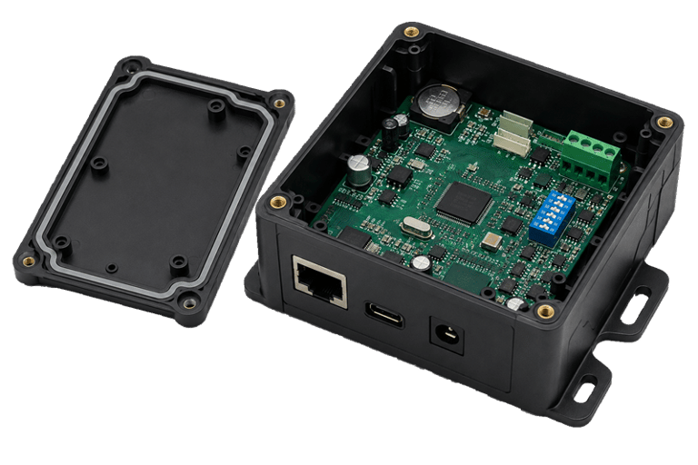
Enclosures designed around your electronics — not retrofitted to them
When your enclosure and your PCB are designed and built in the same facility, by the same team, the result is a product that fits together correctly the first time — not after three rounds of mechanical revisions.
THE INTEGRATION ADVANTAGE
Integrated enclosure and electronics builds available as a complete package — one quote, one timeline, one point of contact.
When your enclosure engineer works with your PCBA team in the same building, every connector cutout is positioned from the actual PCB layout — not from a drawing that might be slightly out of date. Every mounting boss diameter matches the actual standoff being used. Every LED window aligns with the actual component position after reflow, not before.
The alternative — designing an enclosure from a PCB Gerber file at a separate firm — produces an enclosure that is technically correct but practically imprecise. The PCB might be 0.3mm different in real life than in the CAD. The connector body might protrude 0.5mm further than the datasheet shows. The USB port might not clear the enclosure wall by the margin expected. Each of these is a mechanical revision that costs time and money.
We eliminate this category of problem by doing both in the same place. The enclosure is designed with the actual PCB present — or with direct access to the team that is designing it. Fit checks happen before first shots, not after. Assembly issues are resolved in CAD, not in the field.
Enclosure designed from the actual PCB layout — not a drawing approximation
Connector cutouts positioned from actual PCB data
Every USB port, power jack, button, and indicator window is positioned from the actual PCB layout file — not from a dimension taken off a drawing. Cutout positions are accurate to the real board, not to an approximation of it.
Mounting features designed around your actual PCB
Boss diameters, standoff heights, and PCB retention features are specified with the actual PCB dimensions and component heights confirmed. No clearance surprises when the board drops in for the first time.


Design for manufacturability review of the enclosure and the PCBA happens simultaneously — issues in one that affect the other are caught at review, not discovered during assembly. A component that runs hot near a thin wall section gets addressed before tooling is cut.
Enclosure DFM reviewed alongside PCBA DFM


When PCBA and enclosure production are complete, box-build assembly happens in the same facility — no shipping between vendors, no customs delays, no assembly instructions lost in translation. One quote, one schedule, one shipment to you.


Final assembly handled in the same building
Tell us about your enclosure
Whether you have a STEP file ready or just a sketch — tell us what you're building and we'll respond with a quote or a design consultation within 48 hours.
GET A QUOTE
SERVICES
Peakingtech © 2025. · Shenzhen, China · Privacy Policy · Terms of Service
Contact Form
Metal Parts
Peakingtech® is a registered trademark of Peakingtech Co in the United States.
COMPANY
CONTACT