
Capabilities
Specific equipment, tolerances, materials, and certifications — the technical reference for engineers and procurement teams evaluating Peakingtech for a manufacturing project.
Home › About › Capabilities
Capabilities
Team
IPC-A-610 Class 2 | ISO 9001 | Shenzhen-based
TECHNICAL REFERENCE
PCBA ASSEMBLY
Electronics manufacturing specifications
IPC-A-610 Class 2 standard across all builds. NPI from 5 units, production from 50 units. All specifications below are for standard commercial electronics — Class 3 high-reliability specifications available on request.
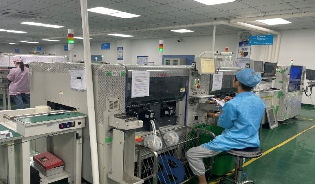
SMT Assembly
Parameter Specification
Minimum component size 01005 (0.4mm ×0.2mm)
Maximum board size 460mm × 460mm
Minimum board size 50mm × 50mm
PCB thickness range 0.4mm – 3.2mm
Maximum panel size 510mm × 460mm
Placement accuracy ±0.05mm (3σ)
BGA minimum pitch 0.3mm
BGA ball count No defined maximum
QFN minimum pitch 0.4mm
Supported lead-free alloys SAC305, SAC405, SnBi
Leaded process Yes (RoHS)
Dual-sided SMT Yes — top and bottom
Mixed SMT/through-hole Yes
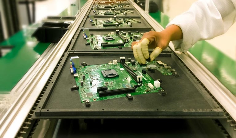
Through-Hole Assembly

Parameter Specification
Manual through-hole Yes — all builds
Selective solder Yes
Wave solder Yes(w/ masking)
Press-fit connectors Yes
Mixed SMT and through-hole Yes — standard
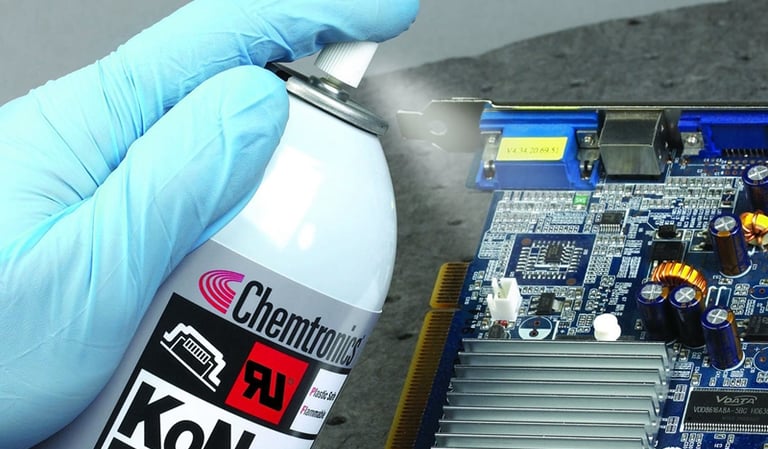
Special Processes

Parameter Specification
Underfill (capillary flow) Yes
Conformal coating Yes
Selective conformal coating Yes
Potting and encapsulation Yes
Staking and adhesive bonding Yes
RF shielding can installation Yes
Heat sink attachment Yes
Battery connection (JST/Molex) Yes
Parameter Specification
In-circuit programming Yes(JTAG, SWD, UART, SPI)
Programming interfaces Custom pogo-pin fixtures
OTA (over-the-air) firmware Yes
Firmware version control Yes
Production programming verification Yes
Secure boot firmware loading Yes


Firmware and Programming
Inspection

Parameter Specification
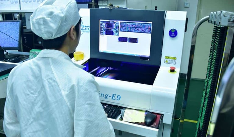
Automated Optical Inspection (AOI) All
AOI detection capability Placement errors, etc.
X-ray inspection Standard for BGA and QFN
X-ray system 2D and CT (3D cross-section)
Manual inspection standard IPC-A-610 Class 2
Solder joint inspection IPC-A-610 Class 2
First article inspection Yes
Incoming component inspection All ICs
Counterfeit detection Certificate of conformance
Parameter Specification
Functional test — bench Available all quantities
Functional test — fixture Available for large runs
Test fixture design Pogo-pin bed-of-nails
Test coverage Per approved specification
In-circuit test (ICT) Available
Flying probe test Available for small volume
Test cycle time (fixture) 30–120s per unit
Test result logging Per-unit pass/fail with SN
Environmental stress screening Burn-in


Testing
Parameter Specification
Build traveler All builds
AOI report All SMT builds
X-ray inspection images All BGA/QFN builds
IPC-A-610 inspection report All builds
First article photographs All builds
Rework log (IPC-7711) All builds requiring rework
Documentation package All production runs
Component traceability All production runs
Certificate of conformance Available on request


Quality documentation
IPC-A-610 Rev G — Acceptability of Electronic Assemblies (Class 2, Class 3 on request)
IPC-J-STD-001 — Requirements for Soldering Electrical and Electronic Assemblies
IPC-7711/7721 — Rework, Modification and Repair of Electronic Assemblies
IPC-1752A — Materials Declaration Management
IPC-9252A — Requirements for Electrical Testing of Unpopulated and Populated PCBs
RoHS Directive 2011/65/EU — Restriction of Hazardous Substances (all builds compliant by default)
ISO 9001:2015 — Quality Management Systems


Standards & Certifications
INJECTION MOLDING
Plastic enclosure and molding specifications
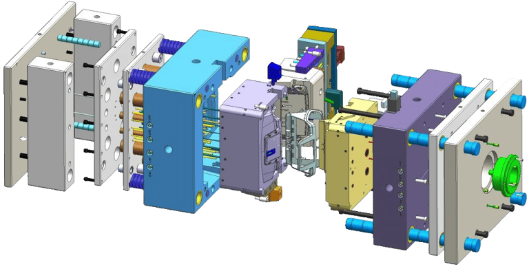
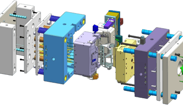
Aluminum rapid tooling for prototype stage, P20 and H13 steel for production. All tooling is client-owned from the moment it is paid for. Tolerances and material properties below are for standard commercial enclosure applications.
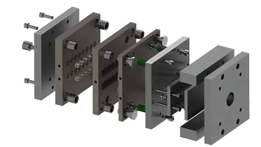
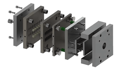
Tooling options and key specifications
Multi-cavity tooling (2, 4, or 8+ cavities) reduces per-part cost at higher production volumes by producing multiple parts per machine cycle. Cavity count decision depends on annual production volume, part complexity, and tooling budget. Multi-cavity tooling is designed and quoted on a per-project basis.
Aluminum
TOOL LIFE: 5,000-10,000 shots
LEAD TIME: 2-3 weeks
COST RANGE: $1,500-$3,000
USE: Design validation, prototype builds
CAVITY OPTIONS: Single cavity standard
SURFACE FINISH: Up to SPI B2
MATERIAL: Most thermoplastics
P20 Steel
TOOL LIFE: 300,000–500,000 shots
LEAD TIME: 4-5 weeks
COST RANGE: $3,000-$8,000
USE: Most production runs
CAVITY OPTIONS: 1, 2, 4 cavities
SURFACE FINISH: Up to SPI A2
MATERIAL: All thermoplastics
H13 Steel
TOOL LIFE: 500,000–1,000,000+ shots
LEAD TIME: 5-7 weeks
COST RANGE: $8,000-$20,000+
USE: High-volume, abrasive materials
CAVITY OPTIONS: 1, 2, 4, 8+ cavities
SURFACE FINISH: Up to SPI A1
MATERIAL: All including abrasive/filled materials
Tooling dimensional specifications
Maximum part size: 400mm × 300mm × 200mm (L × W × H)
Minimum wall thickness: 0.8mm (material-dependent)
Typical tolerance — P20 steel: ±0.1mm on critical dimensions
Typical tolerance — aluminum: ±0.15mm on critical dimensions
Minimum draft angle: 0.5° per surface (1° recommended)
Undercut capability: Side actions, lifters, collapsible cores
Gate types: Edge, sub, pin, hot runner (project-dependent)
Runner system: Cold runner standard, hot runner available
IP rating design: Gasket groove design for IP54–IP68
Material specifications
ABS: easy to mold, good surface quality, paintable, and cost-effective
PC: Preferred when high impact resistance or elevated temperature performance is required
ABS+PC blend: For mid/high-end consumer electronics enclosures - both aesthetics and durability
PP: For enclosures used in chemical, food, or hygiene environments, also used for living hinges
PA/Nylon (PA6, PA66): Applications requiring high mechanical strength, temperature resistance
POM (Acetal/Delrin): High-precision mechanical components requiring tight dimensional tolerance
TPE/TPU: Overmolding onto rigid substrates (ABS/PC) for soft-touch grip surfaces, seals, gaskets
PMMA (Acrylic): Display windows, light pipes, decorative panels for optical clarity/transparency
PC Clear: Transparent panels, lenses, windows for both optical clarity and impact resistance
Mold surface finishes
A1: Mirror polish (diamond, 3µm)
A2: High gloss (diamond, 6µm)
A3: Standard gloss (diamond, 15µm)
B1: Smooth matte (paper, 400 grit)
B2: Matte (paper, 320 grit)
B3: Dull matte (paper, 240 grit)
C1: Fine texture (stone, 600 grit)
C2: Medium texture (stone, 400 grit)
C3: Rough texture (stone, 320 grit)
D1: Blasted (glass bead)
D2: Blasted (dry blast)
D3: Blasted (rough blast)
VDI 12–42 range available on request
Secondary operations
Painting: Single color, multi-color with masking
Spray coating: UV-resistant topcoat, soft-touch coating, rubber-feel coating
Pad printing: Up to 4 colors, repeat registration ±0.1mm
Screen printing: Flat and slightly curved surfaces
UV printing: Full-color photographic quality — flat surfaces
Laser engraving: Permanent, precise — logos, labels, serial numbers
Hot stamping: Metallic foil decoration
Chrome plating: ABS substrate (requires conductive base coat)
Color matching: Pantone, RAL — standard and custom
Assembly: Sub-assembly and full box-build available
Insert molding: Brass inserts, threaded inserts, metal reinforcements
Overmolding: TPE/TPU over rigid substrate, same-shot/secondary molding
IP rating design
Enclosures designed for IP54, IP65, IP66, and IP67 ratings. IP rating design is a Chapter 1 DFM consideration — gasket groove geometry, wall flatness specification, and seal material must be determined at the design stage, not retrofitted after tooling is committed. IP68 design available on request. Tested IP rating certification support (producing test samples) is available for FCC/CE-registered test labs.
METAL FABRICATION
Metal parts and enclosure specifications
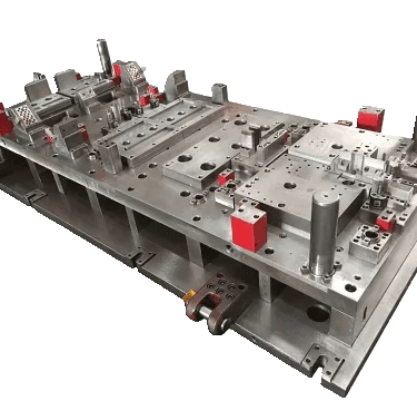
Three metal fabrication processes — sheet metal, CNC machining, and die casting — each with different tolerance capabilities, volume economics, and design requirements. Prototypes from 1 piece across all metal processes.
Sheet Metal
Enclosure panels, brackets, chassis, and structural parts. Flat-to-3D geometry using cutting and bending. Best for thin-wall parts (0.5–3mm) requiring consistent geometry and surface area.
Volume economics:
Prototypes from 1 piece. Production from 10+ pieces. Cost per part decreases with quantity but not dramatically — no tooling amortization barrier.
Laser cut Bend Weld Hardware
SHEET METAL SPECIFICATIONS
Minimum sheet thickness: 0.5mm
Maximum sheet thickness: 6mm (standard), 12mm (special request)
Maximum sheet size: 2,000mm × 1,000mm
Minimum bend radius: 0.5× material thickness
Minimum flange height: 3× material thickness
Minimum hole diameter: Equal to material thickness
Minimum hole-to-edge: 2× material thickness
Laser cut tolerance: ±0.1mm
Formed dimension tolerance: ±0.2mm
Angular tolerance: ±0.5° per bend
Maximum part size (formed): 1,200mm × 600mm × 500mm
Welding: TIG, MIG, spot — all available
Hardware insertion: PEM nuts, standoffs, studs — all available
Minimum prototype quantity: 1 piece
Standard production MOQ: 10 pieces
Precision parts requiring tight tolerances, complex 3D geometry, or material properties unavailable in sheet metal. Housings, heatsinks, brackets with machined features, custom mechanical interfaces.
Volume economics:
Prototypes from 1 piece. Economical at 1–500 pieces. Unit cost decreases slowly with volume — no step-change. High per-unit cost at very high volumes (die casting typically preferred above 1,000+ complex parts).
3-axis 5-axis Turning Precision
SHEET METAL SPECIFICATIONS
Maximum size: 600 × 500 × 400mm (milling)
Minimum feature size: 0.5mm (end mill dia.)
Standard tolerance: ±0.025mm
Precision tolerance: ±0.010mm
Flatness: ±0.02mm/100mm
Parallelism: ±0.02mm
Perpendicularity: ±0.05mm
Surface roughness — standard: Ra 1.6µm
Surface roughness — fine: Ra 0.8µm
Axis capability: 3-axis standard, 5-axis available
Turning/lathe: Yes — cylindrical parts/features
Thread tapping: Yes — metric and imperial
Minimum prototype quantity: 1 piece
Standard production MOQ: 1 piece (no MOQ)
Typical lead time — prototype: 5–7 days
Typical lead time — production: 10–15 days
CNC Machining
High-volume metal parts requiring complex geometry with consistent wall thickness — aluminum or zinc alloy housing shells, connector bodies, structural components. Combines injection-molding-like complexity with metal properties.
Volume economics:
Tooling required (higher one-time cost than injection mold). Economical above 1,000–2,000 pieces. Unit cost well below CNC at high volume. Not suitable for low-volume or prototype applications.
Aluminum alloy Zinc alloy High volume Complex geometry
SHEET METAL SPECIFICATIONS
Processes: High-pressure die casting (HPDC)
Maximum part size: 400mm × 300mm × 200mm
Maximum part weight: 3kg
Minimum wall thickness: 0.8mm (Zn)
Standard tolerance: ±0.15mm
Surface roughness: Ra 1.6–3.2µm (as-cast)
Draft angle: 1–2° internal, 0.5–1° external
Post-machining: Available — for tight-tolerance
Minimum production quantity: 1,000 pieces
Tooling cost range: $5,000–$25,000 per cavity
Tooling lead time: 4–6 weeks
Unit cost range: Varies significantly by complexity — quoted per project
Die Casting

COMPONENT SOURCING
Sourcing and supply chain capabilities
Authorized distributors only — no open market, no grey market, no exceptions. BOM management from initial quote through ongoing production cycles, with continuous lead time monitoring and supply risk alerting.
Authorized distributors only - every BOM line
Every component in every BOM is sourced from authorized distributors in the franchised distribution chain. Peakingtech does not purchase from broker networks, trading companies, or spot market platforms regardless of pricing or availability pressure. When authorized stock is unavailable at acceptable lead time, the response is alternative component qualification — not open market sourcing.
DISTRIBUTOR NETWORK
PRIMARY AUTHORIZED DISTRIBUTORS
Digi-key
Mouser Electronics
Arrow Electronics
Avent
Future Electronics
RS Components
Certificate of conformance required from all suppliers for ICs and active components. Documentation retained and available to client on request.


INCOMING INSPECTION PROTOCOL
Certificate of conformance verification
Lot code and date code recording
Visual inspection
Physical verification
Functional spot-check
Counterfeit electronic components — particularly integrated circuits — are a real and persistent supply chain risk that has affected products from every tier of the electronics industry. The risk is highest for components sourced outside the authorized distribution chain, which is why Peakingtech's no-open-market policy is the most important single counterfeit prevention measure. For authorized distributor stock, the incoming inspection protocol provides a second verification layer.
Multi-layer counterfeit detection at incoming inspection
COUNTERFEIT PREVENTION


SERVICES INCLUDED
Initial BOM sourcing: Full BOM quoted from Gerber/BOM files
Lead time analysis: Line-by-line lead time analysis at each production cycle
Alternative qualification: Authorized alternates qualified for single-source components and long-lead risk mitigation
BOM cost optimization: Volume pricing evaluation, alternative component evaluation for cost reduction
Discontinuation monitoring: Active monitoring for EOL (end-of-life) and NRND (not recommended for new designs) notices
Last-time buy coordination: Coordination of last-time buy quantities for discontinued components
BOM revision management: Design change order support — revised BOM managed per engineering change order
Cross-reference: Cross-reference to verified alternatives for obsolete or unavailable components
BOM management covers the complete component supply lifecycle — from initial BOM review against design files through ongoing availability and pricing monitoring across production cycles. The service is integrated with the production planning cycle rather than treated as a one-time procurement activity.
Complete BOM management from design through ongoing production
BOM MANAGEMENT


ONGOING ACTIVITIES
Lead time monitoring: Component lead time changes monitored continuously. Client alerted when lead time increase affects production schedule or reorder point calculation.
Safety stock planning: Reorder parameters — MOQ, safety stock, reorder point — established at production start and updated as actual demand data replaces forecast.
Supply risk alerting: Single-source components, allocation notices, and supply disruption signals monitored. Alternative qualification initiated proactively when risk is identified.
Supply chain event log: Any supply chain event — price spike, allocation, lead time change, quality incident — documented and shared with client. Builds supply chain intelligence across production cycles.
Ongoing supply chain management is the difference between a manufacturing partner and a manufacturing service. A service executes production orders. A partner monitors the supply chain between orders, alerts to risks before they become crises, and adjusts reorder parameters as demand patterns evolve.
Supply chain management across production cycles


ONGOING SUPPLY CHAIN
CERTIFICATIONS & QUALITY
Quality standards and certifications
All certifications and quality standards that apply across Peakingtech's manufacturing services — consolidated for procurement evaluation and supplier qualification.
Manufacturing Standards
IPC-A-610 Rev G
Acceptability of Electronic Assemblies
Scope: Class 2 standard across all builds — Class 3 available on request
IPC-J-STD-001 Rev H
Requirements for Soldering Electrical and Electronic Assemblies
Scope: Lead-free (primary) and leaded processes
IPC-7711/7721 Rev D
Rework, Modification and Repair of Electronic Assemblies
Scope: All rework performed to this standard — rework log maintained per build
IPC-1752A
Materials Declaration Management
Scope: Component lot and date code traceability — batch and unit level
IPC-9252A
Requirements for Electrical Testing of Unpopulated and Populated PCBs
Scope: Functional and in-circuit test per this standard
ISO 9001:2015
Quality Management Systems — Requirements
Scope: Quality management system certification — applies across all manufacturing services
RoHS Directive 2011/65/EU (as amended)
Restriction of Hazardous Substances in Electrical and Electronic Equipment
Scope: All builds compliant by default — documentation available on request
AQL Statistical Sampling: ISO 2859-1
Levels agreed per product at production planning. Higher-reliability applications may specify tighter levels.
First-Pass Yield Monitoring
Per-batch tracking — IPC-7711 rework
≥ 95% FPY target — consumer electronics
≥ 98% FPY target — high-reliability
Yield threshold agreed per product. Below-threshold batch triggers investigation before next batch.
Component Traceability: IPC-1752A
Batch-level, Unit-level
Lot codes, date codes, and firmware version recorded per build. 3-year minimum retention.
Production Functional Testing: IPC-9252A
Fixture-based: 30–120 seconds/unit (200+ units)
Bench: all quantities
Test specification approved by client before production begins.
Quality system
Peakingtech produces certification test samples to full production standard and maintains BOM configuration lock for certified product configurations, ready for certification testing by accredited third-party test laboratories.
FCC Part 15 / Part 18 — United States
Intentional/unintentional radiators — consumer and commercial electronics
CE Marking — European Union
Radio Equipment Directive (RED), EMC Directive, Low Voltage Directive
UKCA — United Kingdom
Post-Brexit equivalent of CE — same technical requirements
RCM — Australia / New Zealand
Regulatory Compliance Mark — electrical safety, EMC
KC — South Korea
Korea Certification — radio and electrical safety
CCC — China
China Compulsory Certification — required for China market sales
TELEC — Japan
Technical Conformity Mark — radio frequency equipment
SRRC — China (radio)
State Radio Regulation of China — wireless product radio type approval
UL Listing — United States
UL safety certification — on request, extended timeline
Product Certification Support
Have a specific manufacturing requirement?
Share your design files or project requirements — we'll confirm specific capability fit and provide indicative pricing within 48 hours. NDA executed before any file review.
TECHNICAL INQUIRY
NDA before file review · Capability confirmation within 48 hours · No commitment required
SERVICES
Peakingtech © 2025. · Shenzhen, China · Privacy Policy · Terms of Service
Contact Form
Metal Parts


Peakingtech® is a registered trademark of Peakingtech Co in the United States.
COMPANY
CONTACT