
Injection Molding Defects: A Practical Troubleshooting Guide for Engineers and Shop Managers
This guide walks through eleven of the most common injection molding defects. For each one, we define what you're actually looking at, explain the physical mechanism behind it, list the likely root causes, and give you concrete corrective actions in priority order.
PLASTIC ENCLOSURES
Peakingtech Engineering Team
7/10/202614 min read
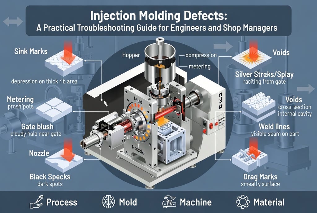

Every injection molding shop fights the same battles: parts come off the press with sink marks, silver streaks, voids, or weld lines, and the team starts turning knobs hoping something works. The problem with knob-turning is that most defects have multiple possible root causes spanning four domains — process, mold, machine, and material — and a fix in one domain can create a new defect in another.
This guide walks through eleven of the most common injection molding defects. For each one, we define what you're actually looking at, explain the physical mechanism behind it, list the likely root causes, and give you concrete corrective actions in priority order. It's written for the people who actually have to solve these problems: process engineers, mold designers, shop managers, and setup technicians.
One principle before we start: diagnose before you adjust. Nearly every defect below has a competing failure mode — raise mold temperature to fix voids and you may create sink marks; slow injection to fix gate blush and you may worsen weld lines. Understanding the mechanism is what lets you pick the right lever instead of trading one reject for another.
1. Unstable Plasticizing (Inconsistent Metering)
What it is
Unstable plasticizing means the machine cannot deliver a consistent amount of melted resin to the barrel shot after shot. It shows up in three ways:
The screw fails to recover (no plasticizing at all)
Recovery (screw-back) time varies noticeably from cycle to cycle
Intermittent short shots
The result is shot-to-shot variation in part weight and dimensions — the silent killer of process capability.
The mechanism
Plasticizing depends on a simple friction relationship: pellets must grip the barrel wall while slipping along the screw surface. When that friction balance is disturbed — by temperature, screw speed, back pressure, or the material itself — conveying becomes erratic and metering drifts.
Root causes
Improper screw speed. Higher screw RPM generally means stronger pellet conveying. If screw speed is too low, feeding weakens and metering suffers. But if it's too fast, pellets can rotate with the screw instead of advancing — same symptom, opposite cause.
Back pressure too high (or too low). Back pressure suppresses air entrapment and stabilizes shot volume, but it also works against forward conveying. Excessive back pressure destabilizes metering.
Wrong barrel temperature profile — especially at the feed throat. The temperature setting under and adjacent to the hopper has an outsized effect on metering. As a rule, temperatures should run high at the nozzle, lower toward the feed section. If the rear zone runs too hot, pellet surfaces begin to melt prematurely, friction between pellets increases, and material sticks to the screw or barrel wall instead of conveying forward. The key point: before the resin reaches its molten state, higher temperature means more friction between plastic and metal, not less.
Regrind in the mix. Recycled material has irregular particle geometry, which increases inter-particle friction and disrupts feeding. Fines and powder stick to the screw and further weaken conveying.
Grade-specific behavior. Lubricated "sliding" grades slip too well against the barrel wall, so screw rotation doesn't convert efficiently into forward conveying. High-impact grades (and materials like PA and LCP) generate high inter-pellet friction — also bad for metering.
Worn check ring (non-return valve) or worn screw. Melt flows backward during injection, and metering becomes unstable no matter what you do with settings.
Undried material.
Corrective actions
Adjust screw speed first. To verify metering instability, measure recovery time over 50–100 continuous cycles, changing RPM in stages and watching for sudden recovery-time excursions. If screw speed alone doesn't solve it, adjust back pressure and barrel temperature together.
Reduce back pressure. Lower back pressure strengthens conveying and stabilizes metering — but don't go so low that air entrapment destabilizes shot volume.
Reduce the rear-zone (feed throat) temperature — gradually. Step down roughly 10 °C at a time. Dropping too far too fast can leave pellets unmelted or even bridge the feed section.
Manage regrind. Match regrind particle size to virgin pellet size as closely as possible, and remove fines/powder.
For problem grades: With sliding grades, if adjusting RPM, back pressure, and barrel temperature together doesn't work, consider a different grade or a different screw design. With high-impact grades, focus on lowering the feed-zone temperature or adding an anti-friction agent.
Inspect the check ring and screw for wear if settings changes don't hold.
2. Gate Blush (Gate Marks)
What it is
Gate blush appears as small, cloudy flow marks concentrated around the gate — often ring- or halo-shaped on the part surface near the injection point.
The mechanism
Gate blush is caused by unstable flow patterns at the gate. In healthy filling, melt fans out from the gate in a smooth, radial front. When flow becomes unstable — jetting, folding, or surging through the gate — the disturbed skin layer freezes against the cavity wall and leaves a visible mark.
Root causes
Process: mold temperature too low; injection speed too fast (through the gate)
Mold: gate too small; impingement-type gate smearing
Material: poor melt flowability
Corrective actions
The strategy is simple: improve the flow condition at the gate.
Raise mold temperature.
Reduce injection speed as the melt passes through the gate. The best way to do this is multi-stage (profiled) injection — slow first stage through the gate, then accelerate for the rest of fill. This keeps cycle time intact while calming the gate region.
Enlarge the gate or relocate it.
Switch to a higher-flow grade or add a lubricant/processing aid.
3. Bubbles (Gas Entrapment)
What it is
Bubbles are raised blisters on the part surface or visible gas pockets trapped inside the part.
Root causes
Air entrainment — inside the barrel:
Screw speed too fast
Back pressure too low
Excessive suck-back (decompression)
Air entrainment — inside the cavity:
Injection speed too fast
Gate too small
Race-tracking (competing flow fronts trapping air)
Sprue taper too steep
Resin degradation generating gas:
Barrel temperature too high
Residence time too long
Screw/barrel oversized for the shot
Contamination with other easily-degraded materials
Undried material.
Corrective actions
Reduce air entrainment in the barrel: lower screw RPM, raise back pressure, keep suck-back modest.
Reduce air entrainment in the cavity: slow injection speed; adjust gate position, size, and geometry; correct sprue draft angle. The key diagnostic here is a short-shot (fill) study — visualize the actual flow pattern, then design your countermeasure around what the melt is really doing.
Suppress degradation: lower barrel temperature (within the resin's recommended window — don't overshoot downward), select an appropriately sized screw, and thoroughly purge the barrel and clean auxiliary equipment to prevent cross-contamination.
Improve venting.
Consider a higher-viscosity grade or additives (e.g., glass microspheres) — high-viscosity materials resist void formation.
4. Voids (Internal Cavities)
What it is
Voids are cavities inside the molded part, and they almost always form at the thickest wall sections. There are two distinct types, and they demand different fixes:
Gas voids — trapped gas collects into pockets as the part solidifies
Vacuum voids — thick-section resin shrinks inward after the skin has frozen, literally tearing a vacuum cavity in the core
An X-ray or careful sectioning distinguishes them: gas voids appear as dispersed bubbles that consolidate; vacuum voids appear as a single cavity pulled open at the thermal center of a thick section.
Root causes of vacuum voids: insufficient effective packing
Vacuum voids are fundamentally a packing (holding pressure) failure — the pressure never effectively reached the thick section to compensate for shrinkage. Common reasons:
Process: switchover (V/P transfer) too early; holding pressure set too low; holding time too short
Mold: gate too small; runners too thin
Machine: worn check-ring assembly (three-piece valve)
Material: high-shrinkage resin
A useful rule of thumb: high mold temperature promotes sink marks; low mold temperature promotes voids. With a cold mold, the skin freezes hard and rigid — internal shrinkage can't pull the surface inward, so it pulls a cavity open inside instead. With a hot mold, the soft skin follows the shrinking core inward and you get a sink mark. Same shrinkage, opposite symptom.
Corrective actions
Deliver more resin during packing:
Process: verify the transfer position, raise holding pressure, extend holding time
Mold: enlarge the gate; enlarge sprue and runner diameters; place the gate as close as possible to the thick section where voids occur
Machine: inspect the screw and check-ring assembly for wear
Slow surface solidification: for vacuum voids, raising mold temperature reduces voids — but watch for the trade into sink marks.
Change material grade or add fillers (glass microspheres, etc.).
5. Sink Marks
What it is
Sink marks are surface depressions caused by resin shrinkage. Semi-crystalline resins lose significant volume as they solidify; because shrinkage rate is roughly fixed for a given material, thicker sections shrink more in absolute terms — which is why sinks appear opposite ribs, bosses, and thick walls.
Root causes
Insufficient effective packing (under-compensation). During hold, packing pressure is supposed to push additional resin in to compensate for cooling shrinkage. When effective packing falls short, the shrinkage exceeds the compensation. Main reasons:
Holding pressure set too low (or unbalanced across gates)
Holding time too short
Gate too small
Runners too thin
Check ring not sealing
Because gate position is critical to pressure transmission, gate into the thick section whenever possible.
Slow cooling → more shrinkage. Thicker walls cool slower and shrink more; higher mold temperature also slows cooling and increases shrinkage. Hot mold + thick wall is the classic sink recipe.
Insufficient cooling time. If the part is ejected before the frozen skin has enough rigidity, the still-shrinking core pulls the soft surface inward.
Corrective actions
Raise effective packing. Increase holding pressure — and to make packing easier to apply, enlarge the sprue, runners, and gate, and move the gate near the sink location.
Lower mold temperature — gradually, to reduce total shrinkage.
Extend cooling time.
Inspect the check ring — both for wear and for contamination preventing it from seating. To inspect, pull the check-ring assembly from the front of the screw and check the contact faces; remove any burnt resin with a brass brush only. Never burn deposits off with a torch — the heat softens the valve metal and dramatically accelerates wear.
Reduce wall thickness where possible. Ribs should be roughly 1/3 of the base wall thickness.
Change grade or add fillers — high-viscosity grades and glass-bead-filled compounds sink less.
6. Black Specks and Gray-Black Streaks
What it is
Black specks are dark points or streaks in the molded part — typically charred (carbonized) resin or foreign contamination.
Root causes
Resin degradation in the barrel:
Material hang-up in stagnation zones
Excessive residence time (barrel too large for the shot)
Temperature too high
The classic stagnation points: the nozzle tip, the front of the barrel, around the check ring, and the back of the screw flights. Also inspect the mating faces between the nozzle, flange, and barrel — any step, mismatch, or damage creates a hang-up ledge where resin degrades.
Inadequate purging. Residue from the previous resin left in the machine, especially in those same stagnation zones and in worn screw areas.
Foreign contamination. Other resins or debris mixed in via the material-handling path or dirty regrind.
Excess trapped gas. If metering starts too early, air wrapped around pellets in the feed zone doesn't escape back through the feed throat; it gets squeezed into the melt and produces gray-black streaking.
Corrective actions
Purge thoroughly until specks stop appearing. Common methods: high-viscosity PE or PP; commercial chemical purging compounds; or pulling the screw and cleaning with a brass brush. For optical parts or other high-spec work, consider dedicating one material to one barrel.
Lower the actual resin temperature. Measure actual melt temperature with a probe rather than trusting controller setpoints — the check-ring area is a prime spot for local overheating. Also verify screw sizing is appropriate.
Shorten residence time — use a machine sized to the mold.
Eliminate contamination: re-purge completely, verify regrind cleanliness, and clean the loaders, hoses, and hoppers.
Vent excess gas — adjust the start of metering so feed-zone air can escape backward.
7. Drag Marks (Slip Marks)
What it is
Drag marks occur when an already-solidified surface skin yields to subsequent pressure and shifts sideways, getting re-pressed against the mold surface. The displaced skin leaves a distinctive smeared pattern, often near gates, sharp corners, and ejector pins.
Root causes
Mold design is the primary driver — drag marks are fundamentally a part-geometry problem. Processing conditions contribute, but their influence is secondary. The three geometries most prone to drag marks:
Corners with no radius (sharp vertical transitions)
Slightly proud (raised) ejector pins
Sharp edges
When the frozen skin at these features slips, the displacement is highly visible. Note that changing gate position or gate count changes flow direction and pressure distribution — and therefore changes where drag marks appear.
Lubricated grades. Grades containing significant oil/lubricant maintain slip but weaken layer-to-layer adhesion in the melt, making skin slippage easier.
Injection speed — in both directions. Slow injection accelerates freezing, raising pressure on the frozen skin and sometimes shifting it. But excessively fast injection also makes the solidified layer easier to displace under pressure.
Mold temperature — in both directions. A cold mold raises cavity pressure, which can shift the skin. An overly hot mold leaves the skin soft and mobile.
Also check whether gates are balanced — imbalance concentrates pressure where you don't want it.
Corrective actions
Adjust injection speed up and down from current settings, ideally with multi-stage injection profiles, and observe.
Adjust mold temperature up and down from the current setpoint.
Modify the mold geometry where the defect appears: radius the corners, set ejector pin heights correctly, break sharp edges. Relocating the gate is also effective.
Change material grade when the geometry can't be modified.
8. Silver Streaks (Splay)
What it is
Silver streaks are white or silvery streaks on the part surface, typically radiating from the gate in the flow direction.
Root causes
Gas from resin decomposition. All resins degrade progressively with temperature. Higher melt temperature or longer residence time → more decomposition products → more splay.
Air entrainment. Screw speed too fast or back pressure too low pulls air into the melt; the result is streaky surface bubbles. Also check sprue taper: excessive sprue taper (over 10°) invites splay — 4–6° is the normal range.
Moisture. Watermark-type splay opens along the flow direction, and the flow front looks rough in unfilled areas. Two sources: inadequately dried material, or a water leak in the mold cavity — always rule out the second.
Undersized vents. Gas that can't escape gets pressed into the part surface.
Material cross-contamination. Residue from a previous run — especially one that runs at lower temperature — generates gas in the current melt. Also be aware that materials loaded with additives (white oil, silicone lubricants, plasticizers like DBP, stabilizers, antistatic agents) are prone to surface delamination and splay.
Corrective actions
Check metering first. If screw RPM is too high or back pressure too low, adjust gradually and observe. Tune to the best point.
Check actual resin temperature against the recommended range (printed on the bag or datasheet). Bring it back into the window and verify screw sizing.
Strengthen drying — and confirm the mold isn't leaking water. Verify both drying temperature and drying time.
Eliminate contamination: re-purge (stagnant resin keeps degrading), verify regrind, clean the material-handling path.
Check vent size and condition.
Check the sprue taper angle.
9. Color Variation
What it is
Color variation is non-uniform color across the part surface — often near the gate versus far from it, occasionally in sharp-edged flow regions.
Root causes and fixes — process side
The two mechanisms are incomplete pigment mixing and material degradation. Process-parameter causes map to fixes as follows:
Material not homogeneously mixed → lower screw speed; raise barrel temperature; raise back pressure
Melt temperature too low → raise barrel temperature; raise back pressure
Back pressure too low → raise back pressure
Screw speed too high → reduce screw speed
Root causes and fixes — machine/design side
Screw stroke too long for the barrel → use a larger-diameter or larger L/D barrel
Melt residence time too short → use a larger-diameter or larger L/D barrel
Screw L/D too low → use a longer L/D barrel
Compression ratio too low → use a higher-compression screw
No shear/mixing section on the screw → specify a screw with shear and/or mixing sections
10. Weld Lines
What it is
Weld lines form wherever two melt fronts meet. Around any hole or core in the part, a weld line is geometrically inevitable — the flow must split and rejoin. The question is never whether you'll have weld lines but how visible and how weak they'll be.
The mechanism
When two flow fronts converge, they do not re-mix — each front has been solidifying at its skin as it advanced (fountain flow). The lower the temperature at the meeting point, the thicker the frozen skin, the more visible the line, and the weaker the bond. Conversely, hotter converging fronts fuse better, gain strength, and nearly disappear.
Root causes
Melt temperature too low at the weld. The conditions that cool the fronts:
Mold temperature too low
Barrel (especially nozzle) temperature too low
Injection speed too slow
Poor material flowability
Pressure too low at the weld. Bond quality at the junction depends on the pressure squeezing the two fronts together. Low holding pressure → visible, weak welds. As solidification progresses, pressure transmission gets harder — so small gates/runners and poor gate placement directly degrade weld quality.
Weak venting at the weld location. Weld points are usually flow ends, where displaced air and gas accumulate. Without a vent there, both appearance and strength suffer — and trapped gas can burn (diesel effect).
Three notes on reinforced materials:
Unfilled resins produce significantly better weld-line quality than filled/reinforced grades.
Weld-line strength depends heavily on filler type and loading; processing aids and flame retardants also hurt weld quality.
In fiber-reinforced materials, fibers at the weld orient perpendicular to flow — a major local mechanical-property penalty. Design accordingly.
Corrective actions
Raise the resin temperature at the weld. Increase mold and barrel temperatures gradually — this is usually the highest-leverage fix, and it improves packing effectiveness too. Faster injection speed also helps by forming the weld before the fronts have cooled.
Raise effective packing. Beyond simply increasing the holding-pressure setpoint, make packing easier to transmit: higher melt temperature, higher mold temperature, faster or multi-stage injection, larger gates, adjusted wall thickness, higher-flow material, and a healthy check ring/screw.
Check the vents. Even when the weld is at a flow end, verify vent depth and width, confirm the vents aren't blocked by mold deposit, and reduce clamp force to the minimum required (over-clamping crushes vents shut). Insufficient venting causes gas burn and cascading defects.
Check gates and runners. If they're undersized, temperature and pressure increases won't fully work. Enlarging gates and runners improves flow and packing simultaneously. Relocating the gate or adding gates repositions the weld line — often the cleanest solution: move it somewhere cosmetically and structurally harmless.
Add overflow wells (cold-slug wells) at the weld location to carry the cold front material out of the part.
A final note on expectations: given mold structure, completely eliminating weld lines is impossible. Don't burn tuning time chasing zero — the correct goal is to reduce the harm the weld line causes to a minimum.
11. Warpage
What it is
Warpage is part deformation after ejection, and its cause reduces to a single phrase: non-uniform shrinkage. Three mechanisms drive it:
Non-uniform temperature (differential cooling)
Non-uniform pressure (differential packing)
Molecular orientation (flow-induced anisotropy)
Corrective actions
a. Gate design
Unify the flow direction. For a long, thin plate, a single gate at the center of the long edge produces radial flow, mixed orientation, and poor flatness. A gate at the short-edge center is better; three gates along the short edge better still; a film/fan gate producing uniform linear flow is best.
Enlarge the gate. Undersized gates (often set small to shorten cycles or ease degating) raise flow resistance, which forces higher injection pressure, stretches and compresses polymer molecules, and locks in residual stress → warp. Remember the pressure-shrinkage gradient: near the gate, pressure is high and volumetric shrinkage low; at the last-filled region, pressure is low and shrinkage high. The longer the flow length, the bigger the differential and the greater the warp.
Position gates for balanced filling. The governing principle: every flow front should reach the cavity extremities and form weld lines at approximately the same time. Fill thick before thin, flat before bent.
b. Mold temperature control
Balance the cooling. A part cooled at 80 °C on one face and 40 °C on the other will bow toward the hot side — the classic warm/warm/cold bimetal effect. Verify circuit layout and check actual surface temperatures (thermal imaging tells the truth).
Add cooling at cores and thick sections. Standing cores trap heat; use baffles, bubblers, or high-conductivity inserts to pull it out.
Select mold materials by thermal conductivity where channels can't reach. Approximate conductivities (kcal/m·h·°C): pure copper 332, pure aluminum 190, silicon-aluminum alloy 141, beryllium copper (2.0C) 104, zinc alloy 94, aluminum bronze 70, carbon steel S50C 46, SKD61 29, SKD11 23, stainless 13Cr 22, stainless 18-8 14. High-conductivity inserts cool dramatically better than tool steel — weigh cost and strength before committing.
c. Processing conditions
Set injection + holding time to gate-seal time as the baseline. If the pressure phase ends before the gate freezes, packing transmission is incomplete and the part can deform.
Watch holding pressure in both directions. Too high, and residual shear and compressive stresses from over-packing cause warp. Too low, and melt flows back out through the gate, generating residual shear stress near the gate; meanwhile the low-pressure center of the part shrinks heavily while the periphery shrinks less, leaving residual tensile stress → warp.
The overall processing philosophy for warp control in one line: high mold temperature, fast injection, low pressure.
The Diagnostic Mindset: Four Domains, One Method
Across all eleven defects, the same four-domain checklist keeps reappearing:
Domain - Typical suspects
Process: Temperatures, speeds, pressures, times, transfer position
Mold: Gate size/position/count, runner sizing, venting, cooling layout, geometry (radii, ribs, wall thickness)
Machine: Check-ring and screw wear, screw design and sizing, barrel condition
Material: Grade selection, drying, regrind quality, contamination, additives
And the same method: change one variable at a time, change it gradually, and verify with data — 50–100 shot metering studies, short-shot fill studies, actual melt-temperature measurement, gate-seal studies. Defect elimination is not knob-turning; it's controlled experimentation.
At Peakingtech, this is the discipline we apply during NPI mold trials — because a defect caught and root-caused at T1 costs a mold tweak, while the same defect discovered in mass production costs a containment, a sort, and a very unhappy customer.
SERVICES
Peakingtech © 2025. · Shenzhen, China · Privacy Policy · Terms of Service
Contact Form
Metal Parts


Peakingtech® is a registered trademark of Peakingtech Co in the United States.
COMPANY
CONTACT