Understanding a Complex System Diagram: A Deep Dive into Interconnected Components
The image you’ve provided offers a fascinating glimpse into a highly detailed and intricate system diagram. This visual representation, likely a schematic or flowchart, showcases a network of components, connections, and processes organized into distinct categories.
3/7/20255 min read
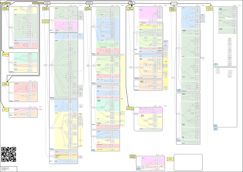
As of March 06, 2025, the image you’ve provided offers a fascinating glimpse into a highly detailed and intricate system diagram. This visual representation, likely a schematic or flowchart, showcases a network of components, connections, and processes organized into distinct categories. While the exact nature of the system—be it mechanical, electrical, software-based, or a hybrid—remains open to interpretation without specific context, the structure suggests a sophisticated framework, possibly related to engineering, technology, or project management. In this blog article, we’ll explore the key elements of this diagram, analyze its potential applications, and discuss how such diagrams serve as critical tools in modern design and development.
Overview of the Diagram
At first glance, the diagram is a colorful tapestry of interconnected nodes and pathways. It is divided into several vertical and horizontal sections, each highlighted with different colors such as green, yellow, blue, pink, and orange. These color-coded sections likely represent different subsystems or functional areas within the larger system. The presence of labels like "Electrical," "Mechanical," "Optical," "Connect," "Control," "Display," and "Power" suggests a multidisciplinary approach, possibly indicating a complex machine, a vehicle, a software architecture, or even an industrial process.
The diagram features numerous boxes connected by lines, which represent the flow of data, energy, or control between components. Some sections are densely packed with sub-components, while others are more sparsely populated, hinting at varying levels of complexity within each subsystem. Additionally, QR codes at the bottom corners suggest that this diagram might be part of a digital or interactive document, allowing users to access more detailed information or updates via a linked resource.
Breaking Down the Key Sections
Electrical Components The leftmost section, labeled "Electrical," is dominated by green and yellow hues. This area likely outlines the electrical infrastructure, including power supply units, wiring, and control circuits. Subcategories such as "Devices" and "Batteries" indicate a focus on energy storage and distribution, which are critical in systems requiring consistent power, such as robotics or automotive designs. The detailed connections suggest a robust network ensuring redundancy and reliability.
Mechanical Systems Adjacent to the electrical section, the "Mechanical" area is marked by orange and red tones. This section might represent physical components like gears, motors, or structural elements. The presence of "Control" and "Storage" subcategories implies a system where mechanical parts are actively managed and possibly stored for maintenance or scalability. This could point to applications in manufacturing or heavy machinery.
Optical and Communication The "Optical" section, highlighted in purple, suggests the inclusion of light-based technologies, such as sensors or displays. Coupled with the "Communication" subcategory, this area might involve data transmission or imaging systems, common in telecommunications or advanced computing environments. The intricate web of connections here indicates a high degree of integration with other subsystems.
Connect and Control The central spine of the diagram, labeled "Connect," serves as a backbone linking various sections. This area, in shades of blue and green, likely represents the interfaces or protocols that enable communication between different parts of the system. The "Control" nodes suggest a centralized management system, possibly a microcontroller or software layer, ensuring synchronized operation across the board.
Display and User Interface The right side of the diagram features a "Display" section in pink and yellow, which could pertain to user interfaces, screens, or output devices. Subcategories like "Project" and "History" might indicate features for monitoring past performance or projecting future states, essential in real-time systems like dashboards or simulation tools.
Power and Regulation The bottom right corner, labeled "Power," emphasizes energy management, with subcategories like "Regulate" and "Convert." This section likely details power regulation circuits, converters, or backup systems, ensuring the stability and efficiency of the entire setup.
Potential Applications
Given the breadth and depth of this diagram, several potential applications come to mind. One possibility is that it represents the architecture of an autonomous vehicle, where electrical systems power the engine, mechanical components handle movement, optical systems include sensors like LIDAR, and the display provides a driver or operator interface. The "Connect" and "Control" sections could house the central processing unit and communication protocols for navigation and safety features.
Alternatively, this could be a schematic for an industrial automation system, where mechanical arms, electrical relays, and optical sensors work in tandem to assemble products. The "History" and "Project" nodes might track production data and forecast maintenance needs, respectively.
Another intriguing possibility is a software architecture diagram for a complex application, where "Electrical" and "Mechanical" symbolize hardware dependencies, "Optical" represents graphical interfaces, and "Connect" denotes API integrations. The "Display" section could then be the frontend user experience, with "Power" managing server resources.
The Importance of System Diagrams
System diagrams like this one are invaluable in engineering and technology fields. They provide a visual roadmap, enabling designers, developers, and stakeholders to understand how individual components interact within a larger ecosystem. This holistic view helps identify potential bottlenecks, optimize performance, and ensure compatibility across subsystems.
For instance, the dense interconnections in the "Connect" section suggest a need for robust error handling and data integrity measures. The color-coding aids in quick recognition of each subsystem’s role, facilitating collaboration among multidisciplinary teams. Moreover, the inclusion of QR codes indicates a forward-thinking approach, allowing for real-time updates or access to supplemental documentation, which is crucial in dynamic projects.
Challenges and Considerations
Creating and interpreting such a diagram is no small feat. The complexity suggests a need for meticulous planning to avoid redundancy or conflicts between components. For example, overlapping connections in the "Control" and "Display" areas might indicate potential points of failure if not properly managed. Additionally, the diagram’s scale implies a large team effort, requiring clear documentation and version control to keep all stakeholders aligned.
From a user perspective, understanding this diagram might require specialized knowledge, especially in deciphering the abbreviations and technical jargon within the nodes. This underscores the importance of accompanying manuals or training, ensuring that even non-experts can grasp the system’s functionality.
Future Implications
As technology continues to evolve, diagrams like this will become even more critical. With the rise of artificial intelligence, Internet of Things (IoT) devices, and smart systems, the need for comprehensive, adaptable schematics will grow. The integration of digital elements, as hinted by the QR codes, points toward a future where such diagrams are interactive, allowing real-time modifications and simulations.
By March 2025, we might see advancements in automated diagram generation using AI, reducing the manual effort required to map out complex systems. This could lead to more efficient design cycles and faster deployment of innovative technologies, from renewable energy solutions to advanced robotics.
Conclusion
The system diagram you’ve shared is a testament to the intricate beauty of modern engineering and design. Its colorful sections and detailed connections reveal a carefully orchestrated network, likely underpinning a cutting-edge application in technology or industry. Whether it’s an autonomous vehicle, an industrial automaton, or a sophisticated software framework, the diagram highlights the importance of integration, control, and visualization in creating functional systems.
As we move forward, tools like this will continue to shape our ability to innovate and solve complex problems. If you’d like a deeper analysis—perhaps identifying specific components or exploring related technologies—feel free to provide more context or ask for a web search to supplement this discussion. For now, this diagram stands as a fascinating snapshot of human ingenuity, ready to inspire and inform the next generation of creators.
SERVICES
Peakingtech © 2025. · Shenzhen, China · Privacy Policy · Terms of Service
Contact Form
Metal Parts
Peakingtech® is a registered trademark of Peakingtech Co in the United States.
COMPANY
CONTACT