Mastering the Art of Soldering: Essential Tips for Electronics Designers and Developers
Soldering is at the heart of electronics design and repair. Whether you're developing a new product, working on a PCB prototype, or repairing an old gadget, the quality of your solder joints can have a direct impact on both the functionality and longevity of your work.
2/18/20259 min read
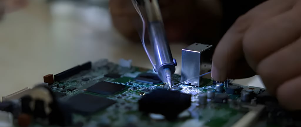
Soldering is at the heart of electronics design and repair. Whether you're developing a new product, working on a PCB prototype, or repairing an old gadget, the quality of your solder joints can have a direct impact on both the functionality and longevity of your work. A poorly soldered joint can lead to circuit failures, unresponsive components, or even total device malfunctions. In this article, we’ll explore essential soldering techniques, discuss common issues, and share expert tips to help both beginners and experienced designers perfect their skills.
Understanding Soldering Basics
What is Soldering?
Soldering is the process of joining two metal surfaces together by melting a filler material (solder) that then solidifies to form a strong, conductive bond. In electronics, this is essential for making electrical connections between components on a PCB.
A good solder joint ensures the circuit performs reliably over its expected lifespan, while a bad joint—such as one with poor electrical conductivity or mechanical strength—can lead to intermittent issues, component failures, or even total system breakdowns.
Types of Solder
There are two primary types of solder that are commonly used in electronics:
Lead-based Solder: Composed primarily of lead and tin, typically 60% tin and 40% lead. It has a relatively low melting point (around 183°C or 361°F), making it easier to work with, especially for beginners. However, due to lead’s toxicity, it is being phased out in favor of lead-free alternatives, especially for consumer products sold in the European Union and North America.
Lead-free Solder: This is an alloy that contains tin, copper, and sometimes silver or bismuth. While it is more environmentally friendly, it has a higher melting point (typically 217-221°C or 423-430°F) and is a little trickier to work with, especially when dealing with fine-pitch components.
Common Soldering Tools
For successful soldering, having the right tools is critical. Here are the essentials:
Soldering Iron: The most important tool in your kit. A soldering iron heats up to the required temperature and melts the solder. Some high-end models feature adjustable temperature controls, allowing you to fine-tune the heat for different tasks. For example, a 60-watt soldering iron is typically sufficient for most work, but a 100-watt model might be necessary for larger components like power transistors.
Flux: This is a chemical substance applied to metal surfaces to prevent oxidation and improve the flow of solder. Without flux, solder tends to form poor joints that may not be conductive or strong. Some solder wire comes with flux inside the core (rosin-core solder), while others require you to apply it separately.
Solder Wire: Available in various gauges (thicknesses), solder wire comes in both lead-based and lead-free varieties. For most standard PCB soldering tasks, a 0.5mm to 1mm diameter solder wire is typically recommended.
Desoldering Pump: This tool helps remove excess solder when you make a mistake or need to reposition a component. Desoldering pumps create a vacuum to suck molten solder out of a joint.
Soldering Iron Stand and Sponge: The stand safely holds the hot soldering iron, while the damp sponge is used to clean the tip between soldering sessions.
Safety Precautions
Soldering involves both heat and chemicals, so always work in a safe environment. Here are some key safety tips:
Ventilation: Soldering produces fumes, especially from flux, that can be harmful when inhaled over long periods. Working in a well-ventilated area or using a fume extractor can greatly reduce exposure to toxic fumes.
Protective Gear: Wear safety glasses to protect your eyes from accidental splashes of molten solder. You should also use heat-resistant gloves if you’re handling components or tools that may get hot.
Preparing for Soldering
A successful soldering project begins with proper preparation.
Cleaning the PCB and Components
Dirt, oil, or oxidation on the PCB or component leads can interfere with soldering, making it difficult for the solder to adhere properly. Before soldering, clean the surface of the PCB with isopropyl alcohol (IPA) and a soft brush. Make sure to scrub gently to avoid damaging delicate pads or traces.
Example Case: When working with a small run of custom PCBs for a client, a designer once discovered that solder wasn’t adhering to the pads as expected. After further inspection, the issue was traced to residual flux left on the board from the PCB manufacturing process. A simple cleaning solved the problem and saved the designer from having to redo the entire assembly.
Choosing the Right Solder and Flux
Solder: Select the right type based on the application. For consumer products or prototyping, a 60/40 lead-based solder (tin/lead) is commonly used due to its ease of use. However, if you're working on products that need to meet international environmental standards (like RoHS compliance), opt for lead-free solder.
Flux: If you’re using lead-free solder, make sure to select flux designed for use with these alloys, as they can require higher temperatures and a different composition of flux for optimal performance.
Example Case: An electronics engineer working on a high-precision medical device encountered issues with lead-free solder forming weak joints. Upon closer inspection, it turned out that the flux used wasn't the best match for the high-temperature alloy, leading to poor flow and cold solder joints. Switching to a better-suited flux resolved the issue.
Setting Up Your Workspace
A clean and organized workspace is essential. Ensure your soldering station is stable, and your tools are within reach. For better precision, consider using a magnifying tool or a microscope for small components. An anti-static mat can help protect sensitive components from electrostatic discharge (ESD).
Essential Soldering Techniques
Now that the preparation is complete, it’s time to master some essential soldering techniques.
1. Tinning the Tip of the Soldering Iron
Before starting, you must “tin” the soldering iron tip—this means applying a small amount of solder to the tip. This process helps with heat transfer and also prevents the tip from oxidizing. A clean, tinned tip ensures a quicker and more consistent soldering process.
Pro Tip: Always clean the tip with a damp sponge between uses to maintain its efficiency.
2. Heating the Joint Properly
One common mistake beginners make is applying solder to the iron tip directly. Instead, place the iron tip on the joint for 1-2 seconds to heat both the component lead and the PCB pad. Once the joint is heated, apply solder, not directly to the tip, but to the joint.
3. Applying Solder Correctly
After heating the joint, apply solder from the opposite side of the iron tip. Feed enough solder to create a small, shiny, concave fillet (a smooth, curved joint). Avoid using too much solder—excess can lead to bridging between pads or components.
Example Case: A designer working on a high-end audio amplifier for a client applied too much solder to the power transistors during testing. This led to an unintended short between two pins, which caused the device to malfunction. After carefully removing the excess solder, the issue was resolved, and the device passed testing.
4. Creating a Good Fillet
A perfect solder joint should have a smooth, shiny, and slightly concave fillet. This means the solder should cover the component lead and PCB pad evenly, ensuring both electrical and mechanical connections are solid.
5. Inspecting and Testing the Connection
After soldering, visually inspect each joint. A good solder joint should be smooth, shiny, and free from cracks or gaps. Use a multimeter to test for continuity and check the solder joint’s electrical conductivity.
Real-World Example: When testing a custom PCB design for an IoT device, a developer noticed intermittent issues. Upon inspecting the solder joints under a magnifying glass, they found tiny cracks forming in the joints of some high-frequency components, likely due to thermal stress. Reworking those joints with more precise heat control solved the problem.
Troubleshooting Common Issues
Even the best solderers run into problems. Here’s how to handle the most common issues:
Cold Solder Joints
Cold solder joints are typically dull and may have visible cracks. This usually happens when the joint doesn’t heat properly. To fix this, reheat the joint and apply a small amount of solder, ensuring the joint is hot enough for proper adhesion.
Excessive or Insufficient Solder
Too much solder leads to a messy, short-circuit-prone joint, while too little solder can create weak connections. Aim for a neat joint with just enough solder to cover the pad and lead.
Example Case: A design engineer once struggled with low yield on a batch of smartphones due to excessive soldering on the charging port connections. The excess solder led to short circuits, causing the phones to fail during the testing phase. By adjusting the soldering technique and using precision soldering tips, the issue was rectified.
Bridging and Shorts
Bridging occurs when excess solder unintentionally connects two adjacent pads, creating a short circuit. To avoid this, use a desoldering pump or braid to remove the solder, and rework the joint.
Desoldering and Reworking Mistakes
Desoldering is an essential skill. Heat the joint until the solder melts, then use a desoldering pump to remove the molten solder. Alternatively, use desoldering braid to soak up excess solder.
Advanced Tips for Precision Soldering
While basic soldering techniques are sufficient for general PCB assembly, complex designs—especially those involving miniature components and high-density circuits—require advanced methods. Here are a few key strategies for ensuring precise, high-quality soldering:
Using a Hot Air Rework Station for SMD Components
Surface-mount devices (SMDs) are increasingly common in modern electronics, offering compact size and high circuit density. However, soldering them manually can be challenging.
When to Use a Hot Air Rework Station:
Soldering or reworking fine-pitch ICs, such as microcontrollers or memory chips.
Removing and replacing damaged or misaligned SMD components.
Reflowing solder paste for high-quality, uniform joints.
How to Use It Properly:
Apply solder paste on PCB pads using a stencil or syringe.
Position the SMD component accurately on the board.
Heat the area with controlled hot air, typically 250-300°C (482-572°F) for lead-free solder.
Watch for the solder paste to melt and reflow, ensuring a secure connection.
Example Case:
A PCB design engineer working on an IoT sensor module faced issues with misaligned QFN (Quad Flat No-lead) packages during hand soldering. Switching to a hot air rework station not only improved alignment precision but also significantly reduced rework time, resulting in higher product reliability.
Preheating Large or Multilayer PCBs
Multilayer PCBs and high-power circuits often absorb heat rapidly, making it difficult to maintain a consistent soldering temperature.
Why Preheat the PCB?
Reduces thermal stress on components.
Prevents cold solder joints due to insufficient heat.
Improves solder flow, especially with lead-free alloys.
Preheating Methods:
Use a PCB preheater to bring the entire board up to 80-150°C (176-302°F) before soldering.
Apply localized heat using a hot air station to pre-warm large ground planes or power traces.
Example Case:
A power electronics designer working on a solar inverter PCB struggled with inconsistent solder joints on large copper pads. Implementing a preheating process drastically improved solder penetration, reducing manufacturing defects and field failures.
Microscope-Assisted Soldering for Ultra-Fine Work
For high-precision applications like medical devices, aerospace electronics, and advanced wearables, soldering under a microscope is a game-changer.
When to Use a Microscope:
Soldering 0402, 0201, or smaller SMD components.
Checking for micro-cracks or insufficient solder joints in high-frequency circuits.
Ensuring correct BGA reflow and ball attachment.
Recommended Equipment:
Stereo microscopes (10x-40x magnification) for manual soldering.
Digital microscopes with image capture for quality control documentation.
Example Case:
An R&D engineer at a medical device startup faced high failure rates in implantable circuits due to microscopic soldering defects. Switching to microscope-assisted soldering reduced production errors by over 60%, ensuring compliance with stringent quality standards.
Troubleshooting and Fixing Soldering Mistakes
Even the most skilled professionals encounter soldering issues. Here’s how to identify and fix the most common problems:
Cold Solder Joints
A cold solder joint appears dull, grainy, or cracked and can cause intermittent circuit failures.
Causes:
Insufficient heat applied to the joint.
Dirty or oxidized component leads.
Moving the component before the solder solidifies.
Fix:
Reheat the joint with a clean soldering iron tip.
Apply fresh flux to improve solder flow.
Let the solder fully cool without movement.
Excessive Solder & Bridging
Too much solder can short adjacent pads, especially in fine-pitch components.
Causes:
Feeding too much solder onto the joint.
Soldering at an incorrect angle, allowing solder to flow uncontrollably.
Fix:
Remove excess solder with a desoldering pump or wicking braid.
Use a fine-tip soldering iron for precision.
Apply flux to help control the flow of solder.
Example Case:
An engineer designing RF circuits for a wireless communication device noticed signal interference due to microscopic solder bridges. Careful inspection and desoldering rework resolved the issue, restoring circuit performance.
Solder Not Sticking to Pads or Leads
If solder beads up instead of bonding, there’s likely a contaminant or oxidation layer present.
Fix:
Clean the surface with isopropyl alcohol (IPA).
Use a freshly tinned soldering iron tip.
Apply flux to break down oxidation before soldering.
Example Case:
A hardware startup encountered PCB assembly issues when their gold-plated pads rejected solder adhesion. Switching to a rosin-based flux improved wetting and solder flow, fixing the problem.
Maintaining and Storing Soldering Equipment
Proper maintenance extends tool life and ensures consistent soldering results.
Cleaning the Soldering Iron Tip
A dirty or oxidized tip reduces heat transfer, making soldering difficult.
Daily Maintenance:
Wipe the tip with a damp sponge or brass wool between joints.
Re-tin the tip before and after each use to prevent oxidation.
Restoring an Oxidized Tip:
Use tip tinner or a mild abrasive cleaner to remove oxidation.
Proper Storage of Solder and Flux
Solder and flux degrade over time, leading to poor joint quality.
Storage Best Practices:
Keep solder wire sealed in a dry, cool environment.
Store flux in airtight containers to prevent evaporation.
Avoid exposure to moisture, which can lead to solder dross formation.
Conclusion: Soldering as an Essential Skill in Electronics Development
Soldering is a fundamental skill for every electronics designer, product developer, and hardware engineer. From basic PCB assembly to high-precision micro-soldering, perfecting this craft leads to more reliable, high-performance products.
Key Takeaways:
✅ Choose the right solder, flux, and tools for your application.
✅ Follow proper preparation and workspace organization for efficiency.
✅ Master essential techniques such as heating the joint correctly and applying the right amount of solder.
✅ Troubleshoot common issues like cold joints, bridging, and oxidation.
✅ Utilize advanced methods like hot air rework, microscope soldering, and preheating for complex designs.
✅ Regularly maintain and store your equipment to extend its lifespan.
By continuously refining your soldering techniques and learning from real-world case studies, you’ll improve product quality, reduce failure rates, and enhance the overall efficiency of electronics development.
If you're looking to deepen your knowledge, consider exploring:
📌 Online courses from MIT OpenCourseWare, Coursera, or IPC standards training.
📌 Professional soldering certifications, such as IPC-A-610 (Acceptability of Electronic Assemblies).
📌 Hands-on practice with development boards like Raspberry Pi and Arduino.
With dedication and the right techniques, you can master soldering and elevate your electronics projects to new heights! 🚀
SERVICES
Peakingtech © 2025. · Shenzhen, China · Privacy Policy · Terms of Service
Contact Form
Metal Parts
Peakingtech® is a registered trademark of Peakingtech Co in the United States.
COMPANY
CONTACT