How to Perform Effective Failure Analysis in Electronics Manufacturing
When an electronic product fails—whether in the production phase or after it reaches the customer—it can lead to costly recalls, reputation damage, and lost revenue. This is why failure analysis (FA) is a critical function in electronics development.
2/18/20254 min read

Electronics manufacturing is a complex process, and despite the best design and quality control efforts, failures can still occur. When an electronic product fails—whether in the production phase or after it reaches the customer—it can lead to costly recalls, reputation damage, and lost revenue. This is why failure analysis (FA) is a critical function in electronics development. A structured and systematic failure analysis approach allows companies to identify the root cause of failures, implement corrective actions, and prevent future defects.
For designers and decision-makers in electronics development, having a solid understanding of failure analysis is essential to maintaining product quality, reducing costs, and improving long-term reliability. This guide will walk you through the key steps in conducting effective failure analysis, with real-world cases and industry insights.
Understanding Failure Analysis in Electronics
What is Failure Analysis?
Failure analysis is the process of investigating and diagnosing why an electronic component or system has failed. It involves a combination of visual inspections, electrical testing, material analysis, and environmental testing to pinpoint the exact cause of the issue. The ultimate goal is not just to fix the failed unit but to prevent similar failures in future production runs.
Common Types of Failures in Electronics
Failures in electronics manufacturing can stem from various sources, including:
Component Failures: Defective ICs, capacitors, resistors, or other electronic parts. Example: In 2016, Samsung's Galaxy Note 7 faced catastrophic battery failures due to faulty battery design, leading to an expensive recall.
PCB Defects: Issues like broken traces, delamination, or poor soldering. Example: A leading automotive electronics manufacturer discovered that micro-cracks in PCB traces caused intermittent failures in vehicle infotainment systems.
Manufacturing Process Errors: Incorrect assembly, contamination, or weak solder joints. Example: Apple had to issue replacements for certain MacBook keyboards because of a faulty butterfly switch design that resulted in unresponsive keys.
Environmental Stress: Heat, humidity, corrosion, or vibration leading to premature failure. Example: In offshore wind turbine electronics, excessive exposure to salt and moisture often leads to corrosion-related failures.
Design Flaws: Poor circuit design, signal integrity issues, or insufficient thermal management. Example: Early LED bulb designs suffered from overheating issues, drastically reducing their lifespan.
Understanding these failure types helps manufacturers narrow down potential root causes quickly and effectively.
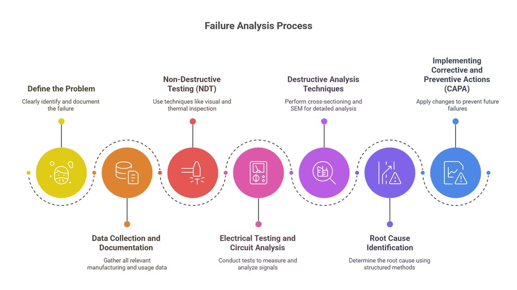
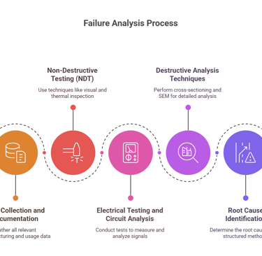
Key Steps in Failure Analysis
1. Define the Problem
Before diving into complex testing, it’s crucial to clearly define the problem. This involves:
Gathering detailed failure reports from production teams or customers.
Identifying symptoms of the failure (e.g., overheating, intermittent operation, complete shutdown).
Understanding the failure's occurrence (Does it happen randomly? Only under certain conditions?).
Classifying failures based on severity and impact on production or end-users.
A well-documented failure report saves time and ensures the investigation stays focused. For example, Tesla uses extensive real-time failure reporting from vehicle sensors to detect early warning signs of component failures.
2. Data Collection and Documentation
Once the failure is defined, collect all available data, including:
Manufacturing records (batch numbers, process logs, component sourcing details).
Test data (factory functional tests, in-circuit testing, burn-in results).
Usage conditions (customer complaints, field reports, environmental conditions).
Using tools like Failure Mode and Effects Analysis (FMEA) can help identify potential weak points before further testing. Case in point: Boeing’s rigorous FMEA process played a role in identifying potential sensor failures in aircraft control systems.
3. Non-Destructive Testing (NDT)
Non-destructive testing is the first step in diagnosing failures without damaging the unit. Common NDT techniques include:
Visual Inspection: Using magnification tools to check for physical damage, solder cracks, or contamination.
X-ray Imaging: Helps detect internal defects in IC packages, solder joints, or PCBs. In one instance, Intel used X-ray imaging to discover hidden solder joint fractures in high-performance processors.
Thermal Imaging: Identifies hot spots or overheating components that indicate circuit stress. Example: Flir thermal cameras are widely used in failure diagnostics for detecting power dissipation anomalies.
4. Electrical Testing and Circuit Analysis
If non-destructive testing doesn’t reveal the issue, the next step is electrical testing:
Multimeter & Oscilloscope Testing: Measures voltage, current, and signal integrity.
Functional Testing: Simulating real-world operating conditions to reproduce the failure. Example: In automotive electronics, test rigs simulate vibrations, temperature fluctuations, and electrical loads to detect intermittent failures.
Curve Tracing: Analyzes semiconductor behavior to check for damaged transistors or diodes.
5. Destructive Analysis Techniques
When non-destructive methods don’t provide clear answers, destructive techniques may be necessary:
Cross-Sectioning (Microsectioning): Cutting a PCB or component to analyze internal structures. Case: A major aerospace manufacturer used this technique to identify delamination in PCBs exposed to high-altitude conditions.
Scanning Electron Microscopy (SEM): Provides high-resolution images of microscopic defects.
Chemical Analysis: Identifies contaminants or corrosion affecting material integrity.
6. Root Cause Identification
After collecting and analyzing the data, it’s time to determine the root cause. Methods like:
5 Whys Analysis: Asking “why” multiple times to trace the failure back to its origin.
Fishbone Diagram (Ishikawa): Visually mapping out possible causes (design, process, material, human error, environment). Example: Toyota famously uses these techniques in its lean manufacturing processes to maintain high quality.
7. Implementing Corrective and Preventive Actions (CAPA)
Once the root cause is identified, corrective and preventive actions must be taken:
Design Improvements: Modifying PCB layouts, adding protective components, improving signal routing.
Process Optimization: Enhancing soldering techniques, improving material handling, or refining quality control.
Supplier Quality Control: Working closely with component suppliers to ensure consistency.
By implementing CAPA effectively, manufacturers can reduce recurring failures and enhance product reliability. In 2020, Apple redesigned the MacBook’s thermal management system to address previous overheating issues.
Conclusion
Failure analysis is more than just troubleshooting defective units—it’s a proactive approach to improving product quality, reducing manufacturing costs, and enhancing customer satisfaction. By following a structured approach—defining the problem, collecting data, conducting thorough testing, and implementing corrective actions—electronics manufacturers can ensure their products are reliable and competitive in the market.
For designers and decision-makers, embedding failure analysis into the development process helps minimize risks, optimize designs, and build a culture of continuous improvement. With the right tools, expertise, and mindset, failure analysis can be a game-changer in achieving long-term success in electronics manufacturing.
SERVICES
Peakingtech © 2025. · Shenzhen, China · Privacy Policy · Terms of Service
Contact Form
Metal Parts
Peakingtech® is a registered trademark of Peakingtech Co in the United States.
COMPANY
CONTACT